What C4 leaves out: time and place
C4 answers how the software is put together: what the parts are, what depends on what, how the systems are wired to each other. That is enormously useful, and it is also the boundary of what it can do. Knowing that the Order API talks to the payment provider tells you nothing about when that conversation happens, in what order, or what occurs when the payment is declined. And it tells you nothing about where the Order API actually runs — one instance or forty, behind what, configured how. Time and place are two questions C4 was never built to answer, and trying to force them onto a structure diagram is how a good diagram turns into a wrong one. This post is about those two gaps, and about the older idea underneath them: no single view of a system is ever complete.
Time: when the parts talk
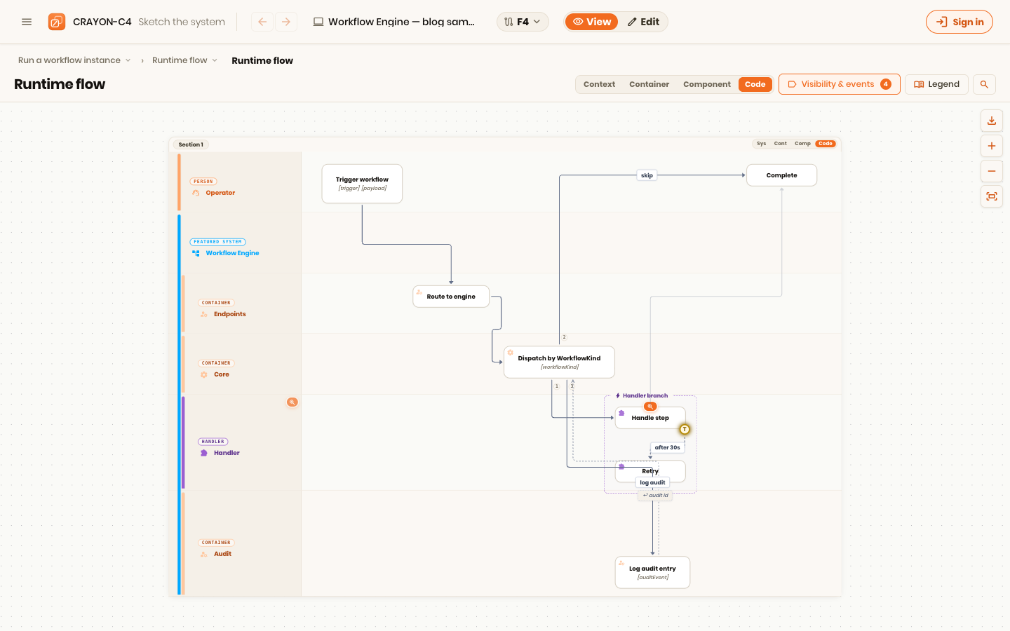
Put a container diagram in front of someone new and the first real question is always a when question. "So when the user clicks Pay, what actually happens?" The structure diagram shows that the web app calls the API and the API calls the provider, but not the sequence, not the decision points, not the unhappy path where the card is declined and stock has to be released. Structure is a what exists view; the question is a what happens view. Narrating arrows out loud is just us papering over a missing diagram.
The behavior notations already exist and are good. A sequence diagram — one of the few pieces of UML that has aged well — shows participants exchanging messages over time, top to bottom, and is precise about ordering and about which calls are synchronous. A swimlane flow puts each actor or system in a lane and routes steps across the lanes; it is the least formal of the options and the one almost anyone can read without training. These are not competitors to C4; they are the piece that picks up exactly where C4 stops. Simon Brown treats them as part of the toolkit for this reason — behavior gets its own dynamic diagram, distinct from the static structure.1
The one weakness they share isn't in the notation — it's that, in most tools, the lane or the participant is just a text label. You type "Order API" in the flow, and your container diagram also has a box labelled "Order API," and nothing connects the two. Rename the container and every behavior diagram naming it is silently wrong. The fix is conceptually simple: the lane should be the architecture element, not merely share its name by coincidence. That binding is the whole reason to keep behavior and structure in one model instead of two folders.
Place: where the parts run
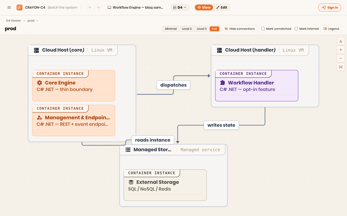
The second gap is deployment, and it matters more than teams expect because it changes on a completely different clock than the code. How the code depends on itself is one thing; how it's deployed is another entirely. Which containers are deployable units, how many instances of each run, how they're configured, how they communicate across a network, what sits in front of them — all of that is driven by scale, by load, by peak moments, by performance targets. Test is not production. None of it belongs on a context or container diagram, precisely because it differs from one environment to the next, while the structure above it stays the same.
That is why deployment gets its own view: a diagram that maps the deployable products onto the infrastructure — virtual environments, or the actual iron — they run on, per environment. It answers a question the abstraction diagrams deliberately refuse. And there's a common anti-pattern worth naming: letting deployment leak upward. The moment a context or container diagram names a load balancer, an API gateway, or a specific cloud service, it has borrowed a liability from a diagram that changes far more often — and it will be wrong the day you re-platform. Keep where it runs in the deployment view, and keep the technology-of-the-moment out of the boxes meant to outlive it.
The older lesson: no single view is complete
Step back and this stops being a story about C4 specifically. A picture says a great deal, but it never says everything — you always lose some context, some detail, depending on which picture you drew. Philippe Kruchten made this the organising idea of software architecture thirty years ago. His 4+1 View Model, published in IEEE Software in 1995, argued that you should describe a system through several concurrent views, each aimed at a different stakeholder's concerns, because no one view can carry them all.2
Kruchten's 4+1 describes five views: the logical view (functionality for the end user), the process view (concurrency and runtime behavior), the development view (how the code is organised for programmers), the physical view (deployment onto hardware), and a +1 of scenarios (use cases) that tie the other four together and validate them.
Read that list against C4 and the mapping is almost embarrassing. C4's abstraction diagrams are essentially the logical and development views — how the software is structured. The process view is behavior — the "when they talk" gap. The physical view is deployment — the "where it runs" gap. C4 is a superb, modern, approachable take on part of the 4+1 picture; it was never meant to be the whole of it. When you find yourself needing a flow diagram or a deployment diagram, you are not compensating for a weakness in C4 — you are doing exactly what the 4+1 model told us to do in 1995, which is to look at the same system from more than one angle.
The practical consequence is the argument for a single model behind all those views. If the "Order API" in the structure view, the lane in the flow view, and the deployed instance in the deployment view are the same element, then a rename is one edit and every view follows. If they're three text labels in three tools, they drift until they describe three different systems. The 4+1 insight — several views of one thing — only pays off when it's genuinely one thing underneath.
Rules of thumb
- Match the diagram to the question. How is it built → C4. When do the parts talk → a flow or sequence diagram. Where does it run → a deployment diagram.
- Bind behavior to structure. A lane or participant should be the architecture element, not a label that happens to match it.
- Keep deployment out of the abstraction diagrams. Load balancers and cloud services belong in the deployment view; they change on a different clock.
- Expect to need more than one view. Kruchten said so in 1995 — completeness comes from several views of one model, not one diagram doing everything.
- Make it one model, not three folders. The multi-view idea only pays off when a rename propagates instead of rotting.
This series is drawn from CRAYON-C4, which is built on exactly this principle: one model, projected into structure, behavior, and deployment views, so the parts stay in sync.
Next in this series: Kruchten's set of views was never meant to be frozen. Security became a first-class perspective; the next one to add is AI.
References
Footnotes
-
Simon Brown, The C4 model for visualising software architecture — the four abstraction diagrams are static structure; dynamic (behavior) and deployment diagrams are supplementary. c4model.com ↩
-
Philippe Kruchten, "Architectural Blueprints — The '4+1' View Model of Software Architecture," IEEE Software, vol. 12, no. 6, November 1995, pp. 42–50. Paper (PDF) ↩