Create a context diagram
The context diagram is where almost every C4 model begins. It shows your system as a single closed box surrounded by the people and external systems around it. The goal: anyone — including non-technical readers — can tell in ten seconds what the system is and who it serves. Unsure this is the level you want? See The three views of a system.
Step 1 — Open the C4 editor
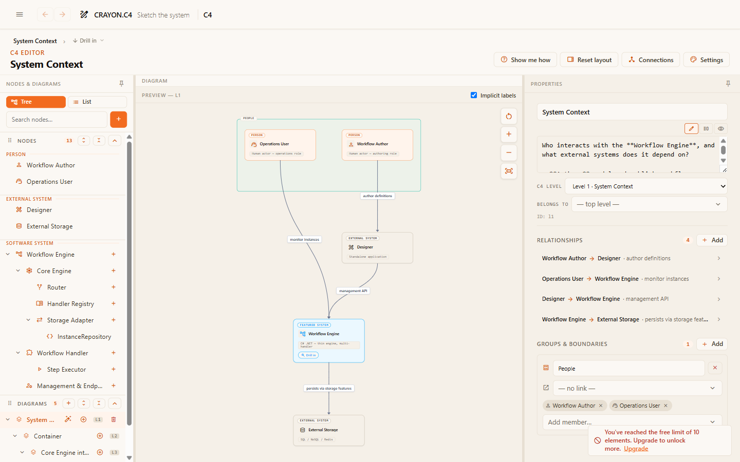
Open the menu and choose the C4 editor. The left tree lists your layers (canvases); select the context layer, or start on the default one in a fresh project.
Step 2 — Add the system box
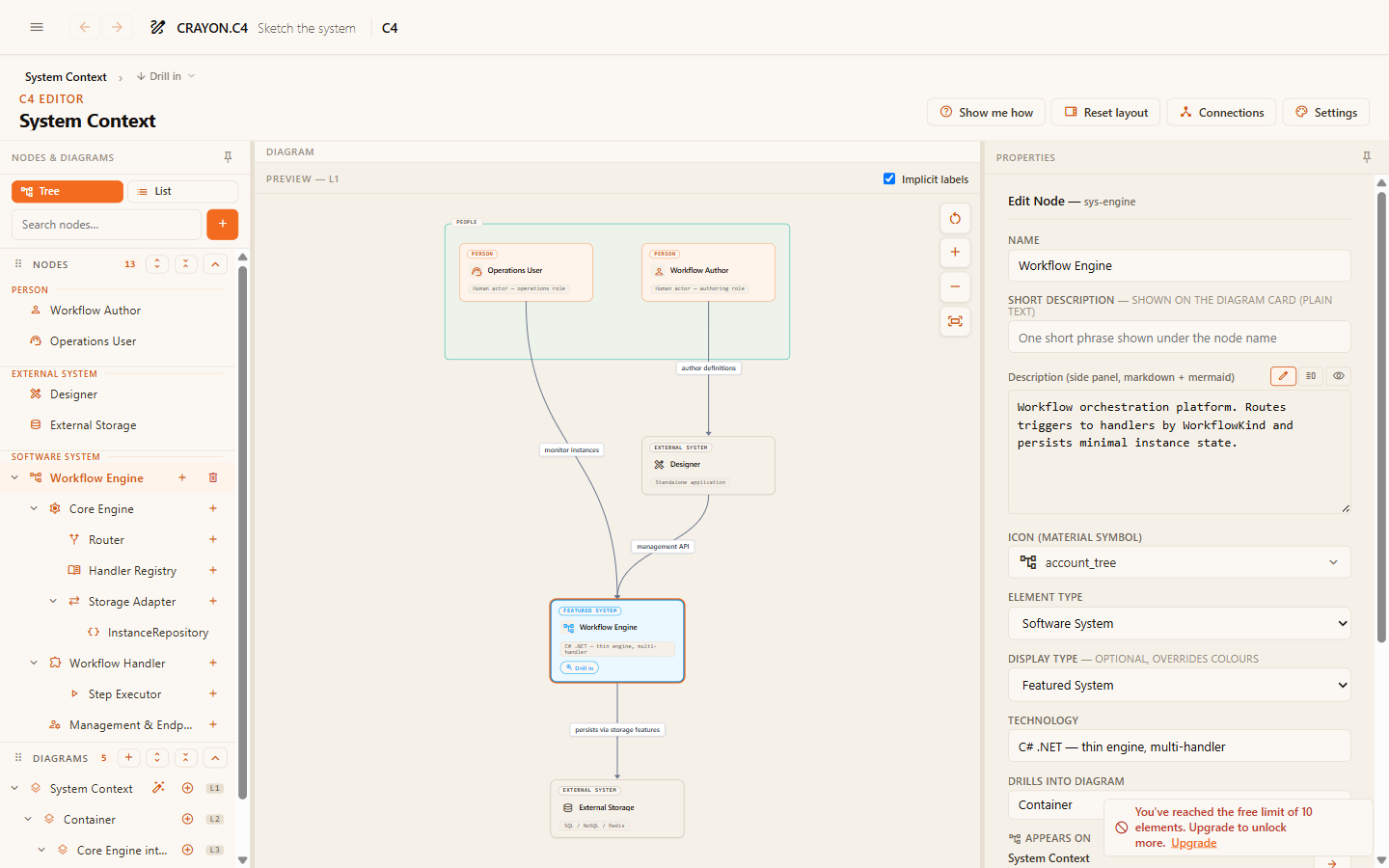
Add an element of type Software System and select it. In the right-hand form, give it a clear name and a one-line description — the description is what readers see when they click the box in the viewer.
Step 3 — Ring it with people and externals
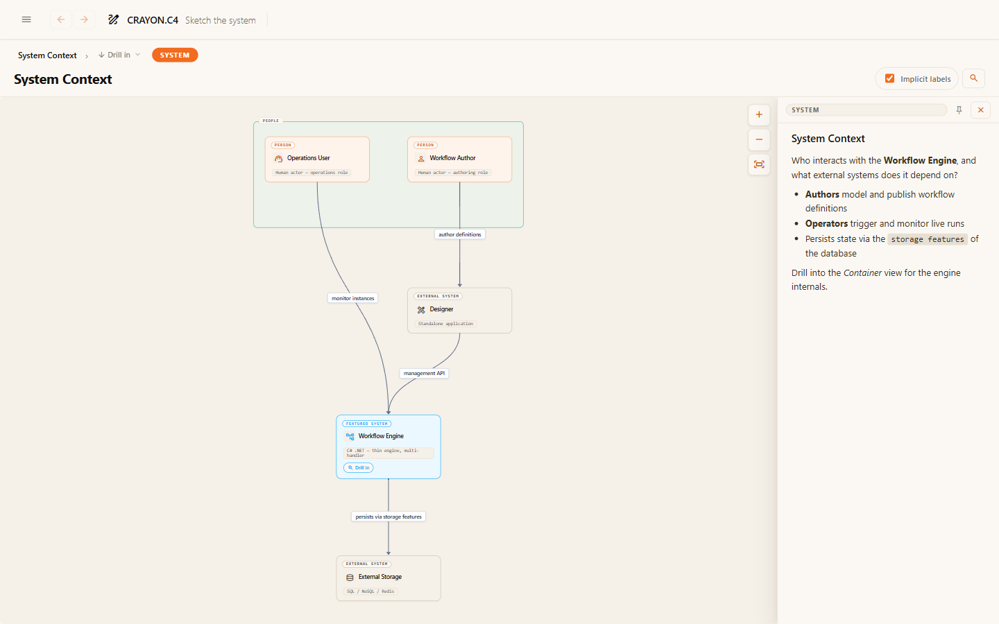
Add a Person element per user role and an External System per outside dependency. Place them around your system box — the system is the center of this picture.
Step 4 — Connect with labeled relationships
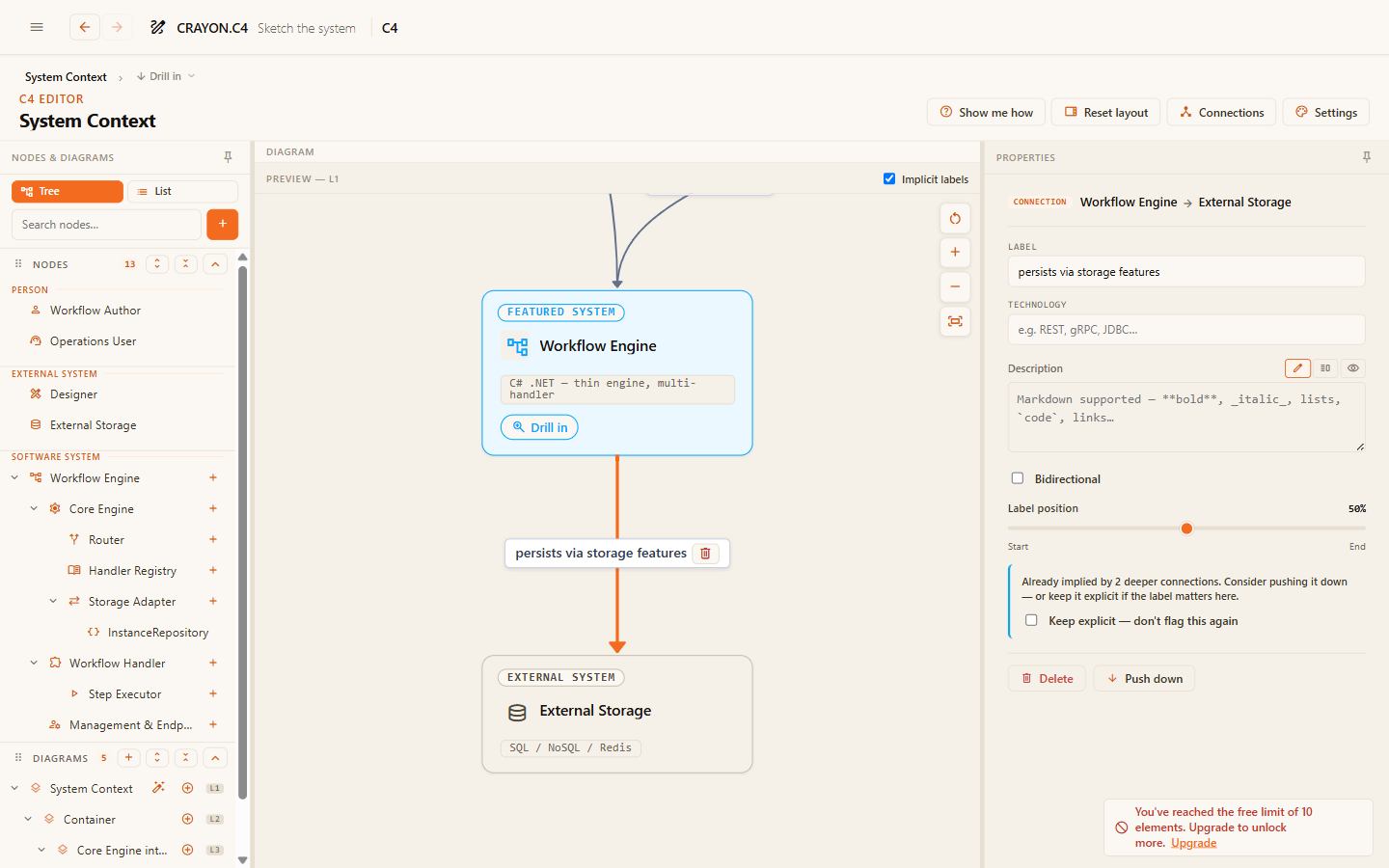
Connect the elements, labeling each arrow with its purpose as a verb phrase. The labels carry the meaning — a context diagram of bare arrows says nothing.
Keep the box closed
A context diagram shows the system as a closed box. Don't show anything inside it — no databases, APIs, or services. The moment a database appears on this canvas, you've drifted into container territory; that belongs on its own level (see Containers & drill-down).
What good looks like
- One system box, clearly the center of the picture.
- A ring of people and external systems around it.
- Every arrow labeled with why the connection exists, not just that it does.
- A reader with no prior context can tell, in ten seconds, what the system is for and who touches it.
Where next
- Add relationships with purpose — make the arrows carry meaning.
- Containers & drill-down — open the box and model what's inside.