Add relationships
A relationship is a directed, labeled arrow between two elements. The label is not decoration — it's the information. A diagram of unlabeled arrows tells the reader nothing about what actually happens.
Step 1 — Drag to connect
Drag from the source element's connection handle to the target element.
Step 2 — Fill in purpose and technology
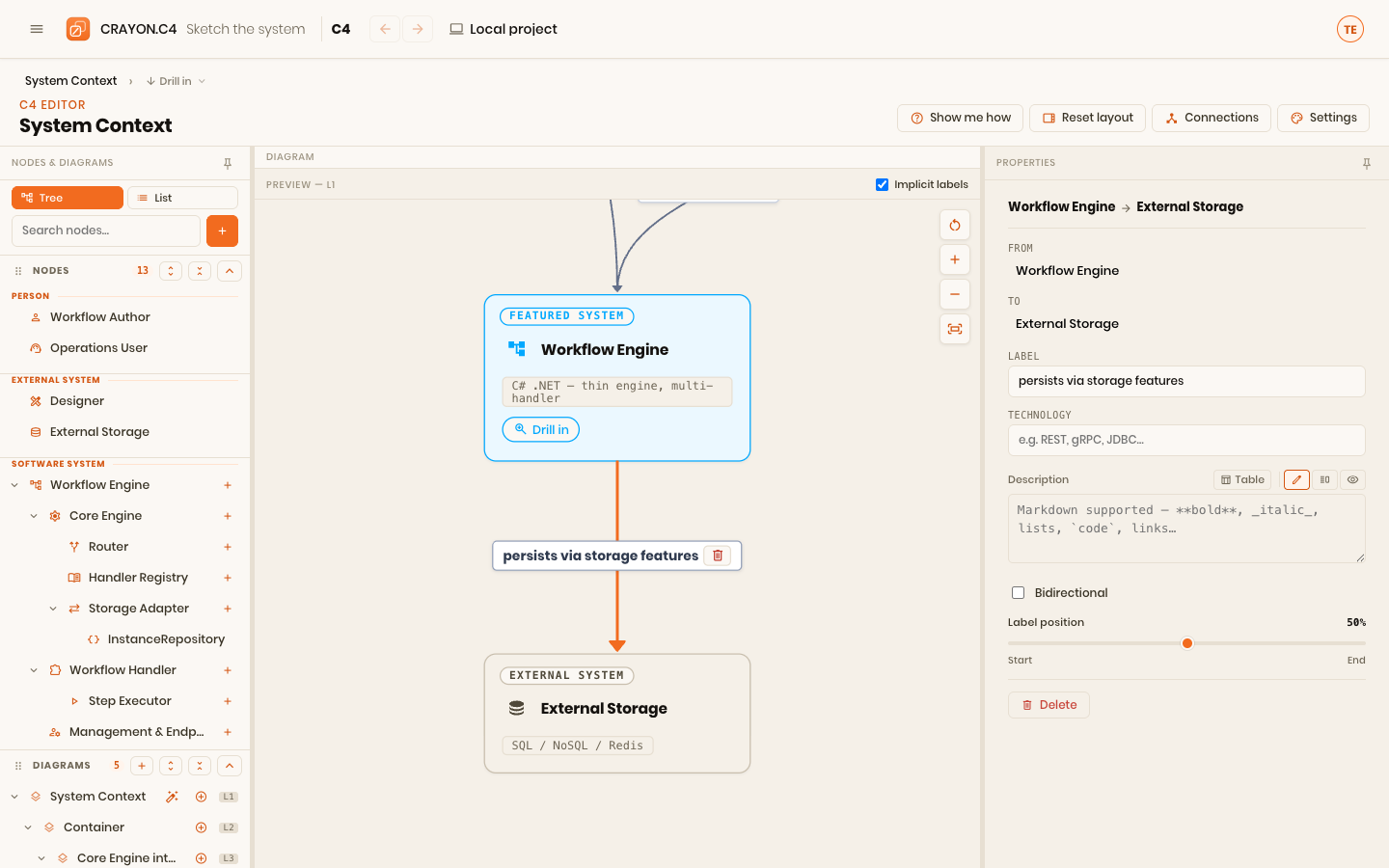
In the relationship's details form, fill in:
- Purpose — what the source does to/with the target, as a verb phrase: "Reads claim data from", "Sends payment instruction to".
- Technology — how, where it matters: "HTTPS / JSON", "JDBC", "AMQP".
Step 3 — Check the direction
The arrow points from the initiator to the thing being acted on.
Show creating a relationship by dragging from a node's connection handle onto another node in the C4 editor, then filling the purpose and technology fields. Key moments: the handle appearing on hover, the drag rubber-band, the drop, the form opening.
Writing good labels
| Weak | Strong |
|---|---|
| "uses" | "Reads policy records from" |
| "connects to" | "Publishes claim events to (AMQP)" |
| (blank) | "Authenticates users via (OAuth 2.0)" |
Direction matters
Direction encodes who initiates, not which way data flows. A service that reads from a database still draws its arrow toward the database, because the service makes the call. Keep this consistent or readers will misread your dependencies.
At different levels
The same two systems may have one coarse relationship at context level ("Exchanges claim data with") that expands into several finer ones at container level ("Reads from", "Writes to", "Subscribes to events"). That's expected — each level labels relationships at its own granularity.
Where a line attaches, and how it runs
Every connection routes itself: the app picks which side of each card the line leaves from and finds a path between them. That is the right default, and on most diagrams you never think about it.
When you do want a particular line to take a particular path, you can pin which side each end attaches to, route the line through corners of your own, and move its label along it — all from the selected connection's Line section and from the line itself on the canvas. Each of those belongs to the diagram rather than to the relationship, and each has a one-click way back to automatic.
→ Shape a connection by hand covers all of it in detail, with pictures.
Curved or straight
A diagram draws its connections either as smooth curves (the default) or with right-angled corners. Select the diagram in the left tree and set Lines on its form. Lines you have routed by hand always follow your own corners, whichever style the diagram uses.
Label a rolled-up line
On a coarser diagram, several deeper connections can roll up onto one line — and no single one of their labels can speak for the rest, so the line shows [*]. Give it a label of its own instead: select the line and fill in Label on this diagram's level. "The systems exchange orders" is a true statement about the coarse pair and about none of the fine ones.
The label belongs to the pair of elements, not to one diagram, so it shows wherever that pair is drawn — and the underlying connections keep their own labels untouched.
You can also do it from the other end. Every connection's Label field carries a collapsed Higher levels (N, M labelled) list: open it to say what this connection means one or two levels up without leaving it. The same list appears in the Connections manager, which has no diagram in context and so offers the ladder alone.
Implicit (rolled-up) relationships and the labels toggle
Some relationships on a coarse diagram aren't drawn there directly — they're rolled up from a deeper level. If two components in different containers talk to each other, that connection surfaces on the container diagram as a relationship between their containers. These implicit relationships carry a small corner badge so you can tell them apart from ones defined on this diagram.
The Implicit labels checkbox (in the viewer's title bar, and the editor's preview header) shows or hides those badges. Turn it off for a cleaner picture; turn it on when you're reasoning about where a connection actually comes from.
Manage all connections in one place
The Connections manager is the central command post for every relationship in the model. Open it from the Connections button in the editor toolbar — the button carries an amber count chip whenever redundant connections are still waiting for review (see below).
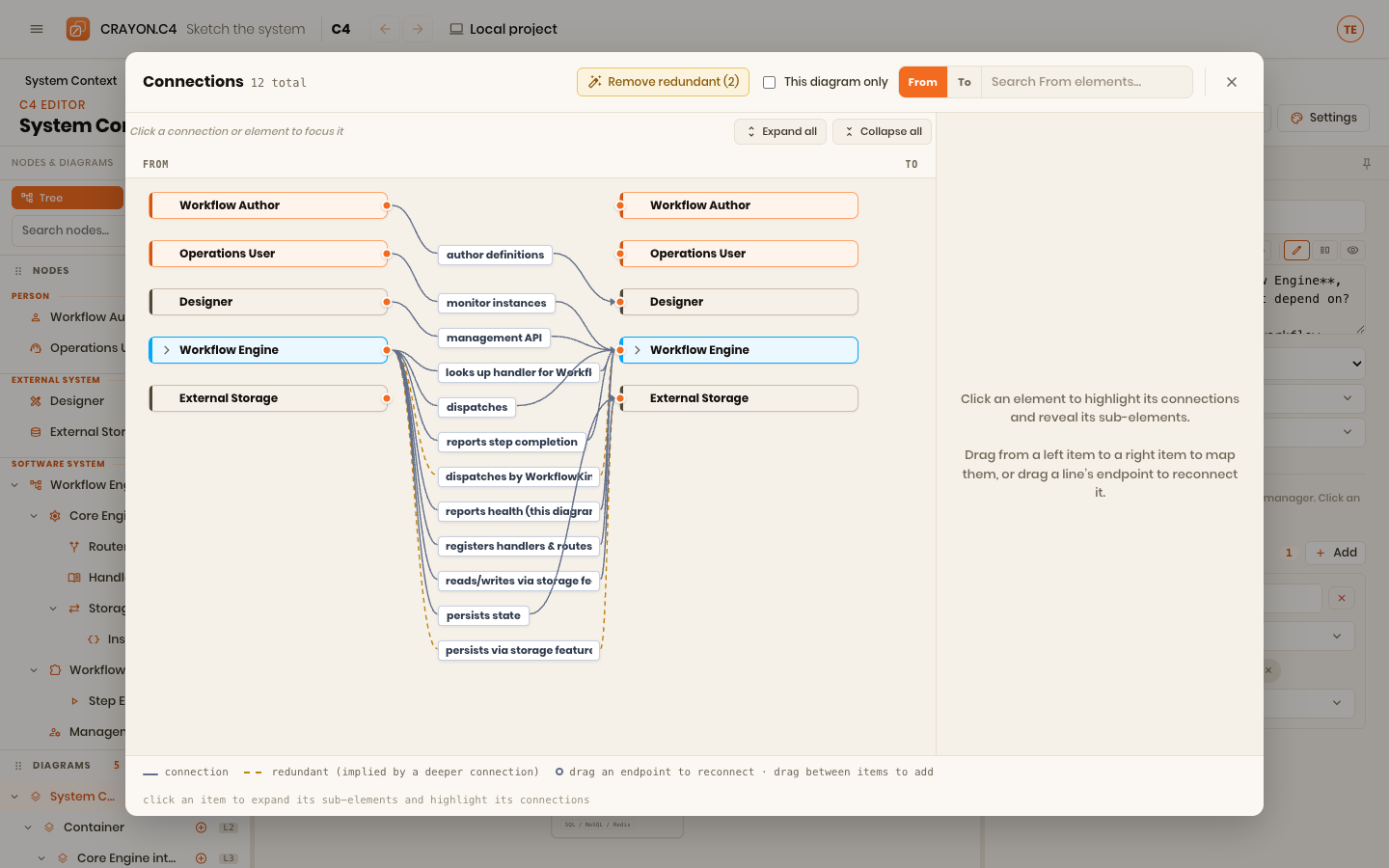
From here you can:
- See all connections at once — listed as a two-column tree (From → To) with every element in the model as a searchable row.
- Find and filter — search the From or To column by element name, or toggle "This diagram only" to show only connections involving elements on the current diagram.
- Add new connections — drag from any From element to any To element in the right column to map them.
- Reconnect endpoints — drag an arrow's endpoint to a different element to re-point it without deleting and recreating.
- Spot redundant connections — the manager marks connections implied by deeper ones in amber: dashed with a dashed-ring badge while they still need a look, solid with a filled-dot badge once you've decided to keep them. For each one you choose: tick Keep explicit in its detail panel (the choice is saved — a kept line stays through clean-ups and stops counting as "to review"), or let Remove redundant (n) delete all still-unreviewed redundant lines at once (connectivity is preserved by the relationships that imply them).
- Edit one connection — click a line to select it and edit its label, technology, and direction in the panel on the right.
Editing a connection
When you select a connection (by clicking an arrow on the canvas or clicking a line in the Connections manager), its details appear on the right:
Endpoints — the From and To dropdowns let you re-point the connection to different elements without losing its label or metadata. Useful for fixing a misdrawn connection or moving a relationship to a different element after a refactor.
Sides and routing — directly under the endpoints, because where a line attaches and how it runs are the same question you came here from the canvas to answer. See Where a line attaches, and how it runs.
Line style — the kind of line this is: Default line, or any style your project defines (colour, thickness, solid/dashed/dotted). See Styling and appearance.
Label — the purpose of the connection ("Reads policy records from", "Publishes events to"). The label is the information; an unlabeled arrow says nothing.
Technology — optional detail on how ("REST / JSON", "JDBC", "AMQP"). Omit if it's not relevant to understanding.
Description — optional markdown for longer explanation, visible in the side panel on the viewer.
Bidirectional — check this if the connection is truly two-way (synchronous request-reply, peer-to-peer sync). Most connections are one-way (initiator → target); bidirectional arrows are rare and should be used sparingly.
Label position — a slider to move the label along the edge (useful on busy diagrams to avoid crowding).
Delete — remove the connection entirely.
Edge actions on the canvas
When you click or hover over a connection arrow in the editor, a context menu appears. In addition to the endpoint-reconnect affordance (drag an endpoint left or right to move it), the menu offers "Pull down to a child on this diagram" — a shortcut to re-anchor the relationship onto a child element without manually recreating it.
Where next
- Containers & drill-down — see relationships climb between levels.
- The C4 model — why the labeled edges are the model.